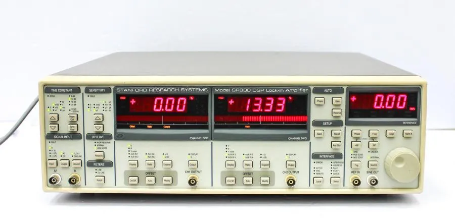
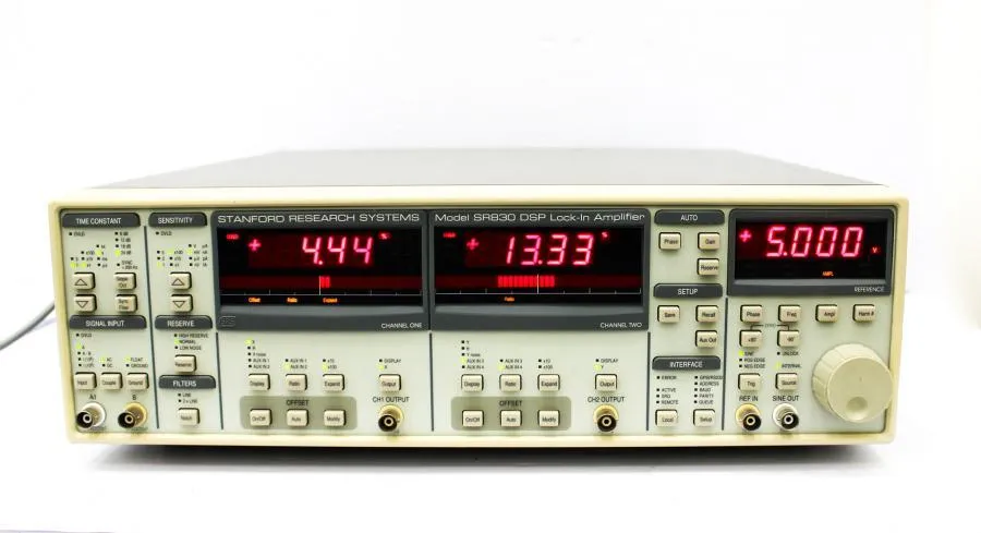
Standford Research Systems Model: SR830 DSP Lock-In Amplifier
- Make Stanford Research Systems
- Hertz 50Hz/60Hz
- Model SR830 DSP Lock-In Amplifier
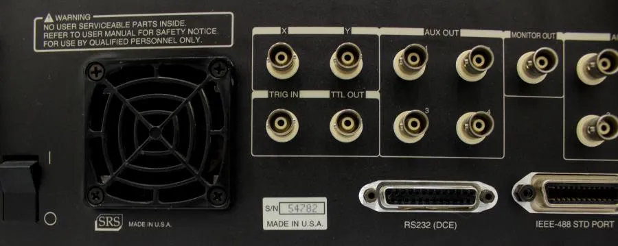
- Serial 54782
- Weight 29
- Voltage 120V
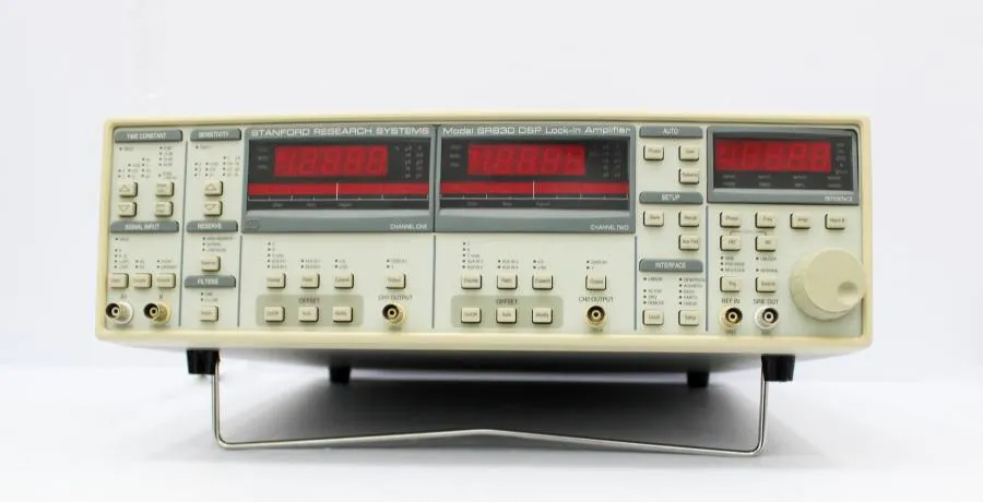
- Working Working
- Includes Power Cord
- Warranty 30-Day Warranty, 100% Parts and Labor
- Dimensions 27×24×13 in
- Shipping Type FedEx Ground
- Item Condition Pre-owned
Standford Research Systems Model: SR830 DSP Lock-In Amplifier
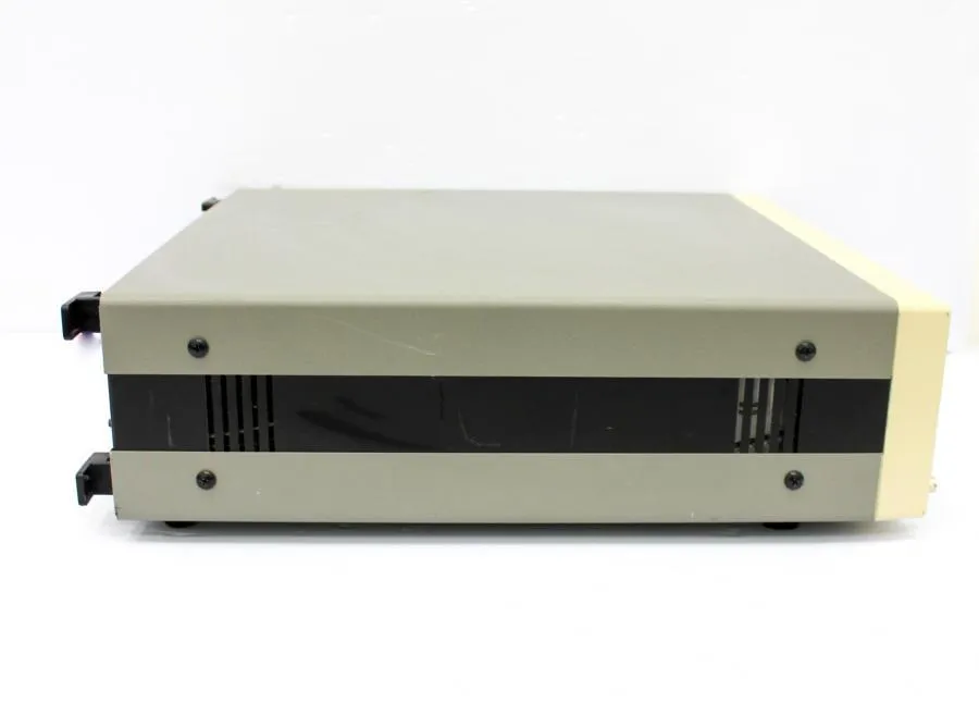
**This Unit has been tested to specifications. Has slight cosmetic blemishes for regular use. See photos for further details.
The SR830 DSP Lock-In Amplifier provides high performance at a reasonable cost. The SR830 simultaneously displays the magnitude and phase of a signal. The instrument utilizes digital signal processing (DSP) to replace the demodulators, output filters, and amplifiers found in conventional lock-ins. The SR830 provides uncompromised performance with an operating range of 1 mHz to 102 kHz and 100 dB of drift free dynamic reserve.
Features
- 1 mHz to 102.4 kHz frequency range
- >100 dB dynamic reserve
- 5 ppm/°C stability
- 0.01 degree phase resolution
- Time constants from 10 µs to 30 ks (up to 24 dB/oct rolloff)
- Auto-gain, -phase, -reserve and -offset
- Synthesized reference source
- GPIB and RS-232 interfaces
The SR810 and SR830 have differential inputs with 6 nV/√Hz input noise. The input impedance is 10 M, and minimum full-scale input voltage sensitivity is 2 nV. The inputs can also be configured for current measurements with selectable current gains of 106 and 108 V/A. A line filter (50 Hz or 60 Hz) and a 2× line filter (100 Hz or 120 Hz) are provided to eliminate line related interference. However, unlike conventional lock-in amplifiers, no tracking band-pass filter is needed at the input. This filter is used by conventional lockins to increase dynamic reserve. Unfortunately, band pass filters also introduce noise, amplitude and phase error, and drift. The DSP design of these lock-ins has such inherently large dynamic reserve that no band pass filter is needed.
Specifications
Voltage inputs: Single-ended or differential
Sensitivity: 2 nV to 1V
Current input: 106 or 108 V/A
Input impedance
Voltage: 10M+25 pF, AC or DC coupled
Current: 1 k to virtual ground
Gain accuracy: ±1% (±0.2% typ.)
Noise (typ.): 6 nV/√Hz at 1 kHz
0.13 pA/√Hz at 1 kHz (106 V/A)
0.013 pA/√Hz at 100Hz (108 V/A)
Line filters: 50/60Hz and 100/120Hz (Q=4 )
CMRR: 100 dB to 10 kHz, decreasing by
6 dB/oct above 10 kHz
Dynamic reserve >:100 dB (without prefilters)
Stability: <5 ppm/°C
Reference Channel
Frequency range: 0.001Hz to 102.4 kHz
Reference input: TTL or sine (400mVpp min.)
Input impedance: 1M, 25 pF
Phase resolution: 0.01° front panel, 0.008° through computer interfaces
Absolute phase error: <1°
Relative phase error: <0.001°
Orthogonality: 90° ± 0.001°
Phase noise Internal ref: Synthesized, <0.0001° rms at 1 kHz
External ref: 0.005° rms at 1 kHz (100ms time constant, 12 dB/oct)
Phase drift: <0.01°/°C below 10 kHz, <0.1°/°C above 10 kHz
Harmonic detection: 2F, 3F, ... nF to 102 kHz (n < 19,999)
Acquisition time: (2 cycles+5ms) or 40ms, whichever is larger
Demodulator
Stability: Digital outputs and display: no drift. Analog outputs: <5 ppm/°C for all dynamic reserve settings
Harmonic rejection: –90 dB
Time constants: 10µs to 30 ks (6, 12, 18, 24 dB/oct rolloff). Synchronous filters available below 200Hz.
Internal Oscillator
Range: 1mHz to 102 kHz
Frequency accuracy: 25 ppm+30µHz
Frequency resolution: 4½ digits or 0.1mHz, whichever is greater
Distortion: –80 dBc (f<10 kHz), –70 dBc (f>10 kHz) @ 1Vrms amplitude
Amplitude: 0.004 to 5Vrms into 10 k (2mV resolution), 50 output impedance, 50mA maximum current into 50 Amplitude accuracy 1%
Amplitude stability: 50 ppm/°C
Outputs: Sine, TTL (When using an external reference, both outputs are phase locked to the external reference.)
Displays
Channel: 1 4½-digit LED display with 40-segment LED bar graph. X, R, X-noise, Aux 1 or Aux 2. The display can also be any of these quantities divided by Aux 1 or Aux 2.
Channel 2: (SR830) 4½-digit LED display with 40-segment LED bar graph. Y, θ, Y-noise, Aux 3 or Aux 4. The display can also be any of these quantities divided by Aux 3 or Aux 4.
Offset: X, Y, R can be offset up to ±105% of full scale.
Expand: X, Y, R can be expanded by 10× or 100×
Reference: 4½-digit LED display
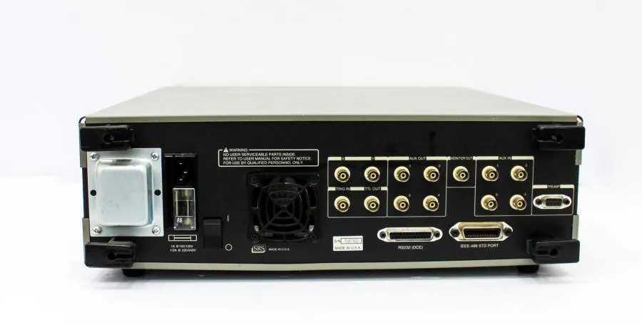
Inputs and Outputs
CH1 output: X, R, X-noise, Aux 1 or Aux 2 (±10V), updated at 512Hz.
CH2 output (SR830): Y, θ, Y-noise, Aux 3 or Aux 4 (±10V), updated at 512Hz.
X, Y outputs In: -phase and quadrature components (rear panel) (±10 V), updated at 256 kHz
Aux. A/D inputs 4: BNC inputs, 16-bit, ±10V, 1mV resolution, sampled at 512Hz
Aux. D/A outputs 4: BNC outputs, 16-bit, ±10V, 1mV resolution
Sine out Internal: oscillator analog output
TTL out Internal: oscillator TTL output Data buffer The SR810 has an 8k point buffer. The SR830 has two 16k point buffers. Data is recorded at rates to 512 Hz and read through the computer interfaces.
Trigger in (TTL): Trigger synchronizes data recording
Remote preamp: Provides power to the optional SR55X preamps
Interfaces: IEEE-488.2 and RS-232 interfaces standard. All instrument functions can be controlled and read through IEEE-488.2 or RS-232 interfaces.
Power: 40W, 100/120/220/240VAC, 50/60Hz
Testimonials
“REUZEit has been a great partner for our used equipment needs and always provide timely updates of new arrivals of consigned equipment.”
“Great company to work with. Tammy completed our first international equipment shipment with ease.”
“Fast response, open to adjusting schedule as needed, and great customer interaction.”
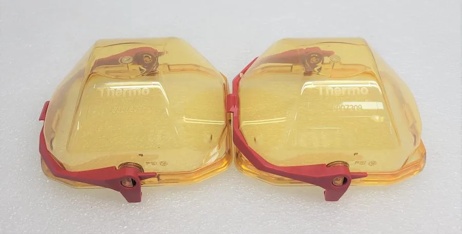
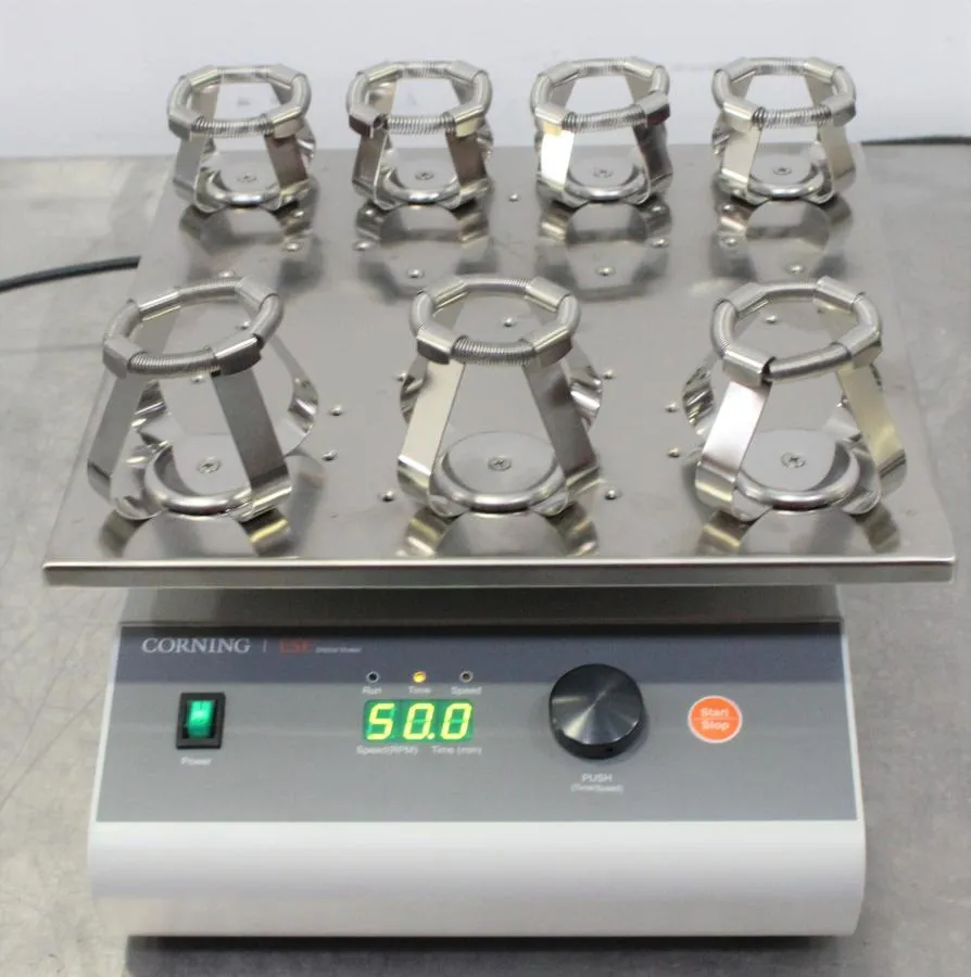
Thermo Scientific 75007309 ClickSeal Biocontainment Lid (Set of 2)
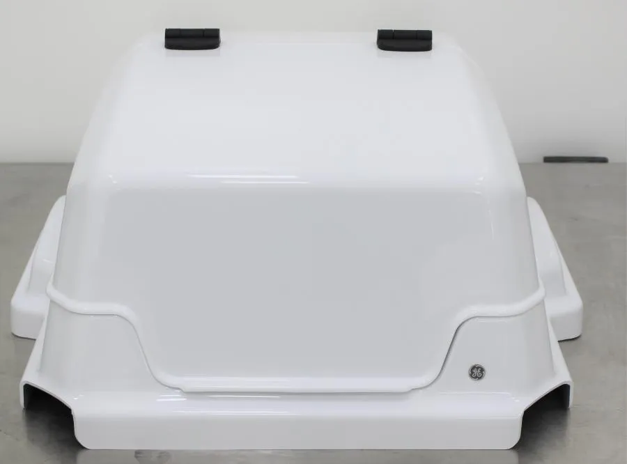
GE Healthcare Lid 10 for Xuri Cell Expansion CLEARANCE! As-Is
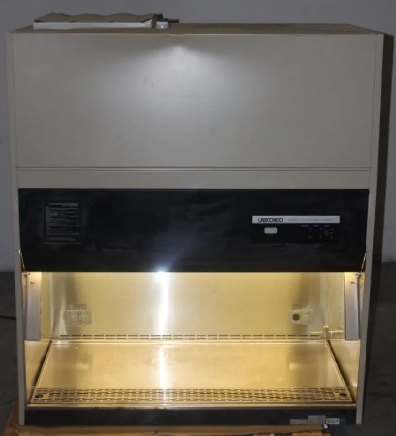
Labconco 5ft Purifier Class II Biosafety Cabinet CLEARANCE! As-Is